Tech Tip 28
| Tech Tip # 28 |  |
This procedure is specifically directed towards a Honda TRX300 Utility ATV, but the internal starter motor section is applicable to many models of ATV, whether 2 brush or 4 brush models.
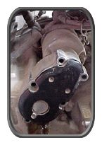
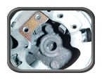
Start by removing the 5 bolts holding on the starter motor reduction gear cover.
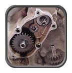
With the cover removed, the upper and lower set of reduction gears can be removed.
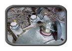
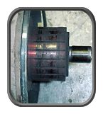
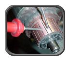
Next, remove the 10mm nut from the terminal stud of the starter motor. Then loosen and remove the two 8mm bolts holding the starter motor to the crankcase.
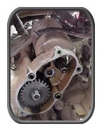
Wiggle the starter motor to break the seal tension and remove the motor from the left case as shown.
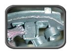
Loosen the two long starter motor case bolts, remove them and pull the brush cap off motor case. This starter motor has worn out brushes and is full of powdered brush material.
With the shortening of the brushes, the spring tension holding them against the communtator decreased to the point there was electrical arc’ing as shown at right.
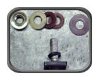
Remove the Positive (+) brush and terminal from the motors brush cap. Make sure you keep the order of washers straight. They will be needed to provide insulation.
When removing brushes from the brush holder, use needlenose pliers to position the flat spring as shown to allow removal of the brush. If the spring slips off, it requires some force to replace.
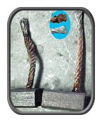
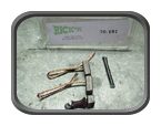 Open the package of aftermarket replacement brushes for your model of starter. In this case we are using “Ricks” replacement brushes. The package contains two brushes, with long leads, and a length of woven insulation. The worn out factory brush is shown at the bottom. Two types of brushes will cover most of the ATV starter motors out there, 2 brush Nippon-Denso Mitsuba Permanent Magnet starter motors and 4 brush Permanent Magnet Mitsuba starter motors.
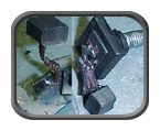
Here we see how each factory brush is soldered to its mount. The Negative (-) is attached to the brush holder plate and the Positive (+) is attached to the terminal stud.
Before we go to the trouble of soldering on new brushes, we have to determine if there was a reason the starter motor stopped working besides the worn down brushes and burnt communtator.
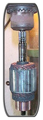
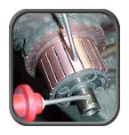
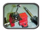
To do that we need to clean up the copper contacts of the communtator. The easiest way is to chuck up the armature in either a drill press or a stationary drill. Run the drill at a high speed. Use a thin strip of Emory Cloth and a little WD-40® for lubrication and gently abrade away the burnt top coating.
Make sure you remove material evenly from top to bottom. Remove no more material than necessary. When the surface is flat from one segment to the next, stop.
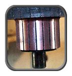
Use a sharp object to remove any debris from between the copper segments.
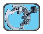
Set a VOM (Volt-Ohm Meter) to continuity and check all ajacient copper segments. ALL must read 100% continuity. If any segment is “dead”, replace the armature. The easiest way is to leave one electrode on one segment and run the other around the contacts while watching the meter.
Next the communtator’s insulation must be checked. Place one electrode on the center shaft and run the other electrode over ALL the copper contacts. If there is ANY continuity, replace the armature.
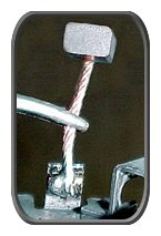
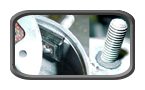
Now that you know the starter motor is OK, save for brushes, lets replace them! Measure the lead length of the factory leads on the brushes and cut your replacement brushes to the same length. Flux them then “Tin” them with solder. See inset.
Next solder the Tinned lead to the brush plate.
Note: Forceps (medical or mechanical) work great for holding the lead.
The Positive (+) lead needs to have a section of the woven insulating sleeve placed over the lead before soldering it on the Positive (+) terminal stud.
Place the brushes in the slots, orientated so the brushe’s curve corrisponds to the curve of the armature. Slide the spring back into position.
 Slide the Positive (+) terminal stud carefully into the brush cap as shown. Note the position of the rubber washer, it MUST be positioned as shown. Replace ALL the fiber washers previously removed, in the exact reverse order of removal.